Page 1 of 2 12 LastLast
Results 1 to 25 of 29

Thread: How To: Assemble A Forged MZR DISI Motor

  1. #1
    Sponsor
    BlueStreak's Avatar
    Join Date
    Oct 2007
    Posts
    1,183
    Thanks
    39
    Thanked 34 Times in 13 Posts
    Mentioned
    34 Post(s)
    Tagged
    0 Thread(s)

    Default How To: Assemble A Forged MZR DISI Motor

    I have been meaning to do this for a while but have procrastinated like no other. Its about time I got to it.

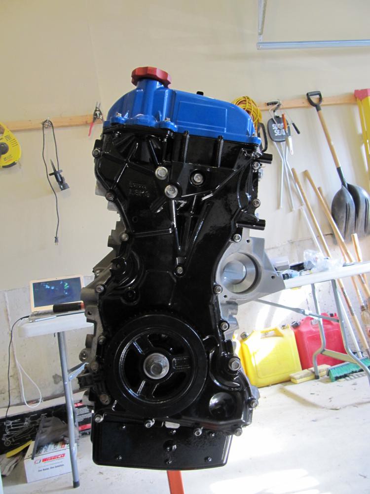
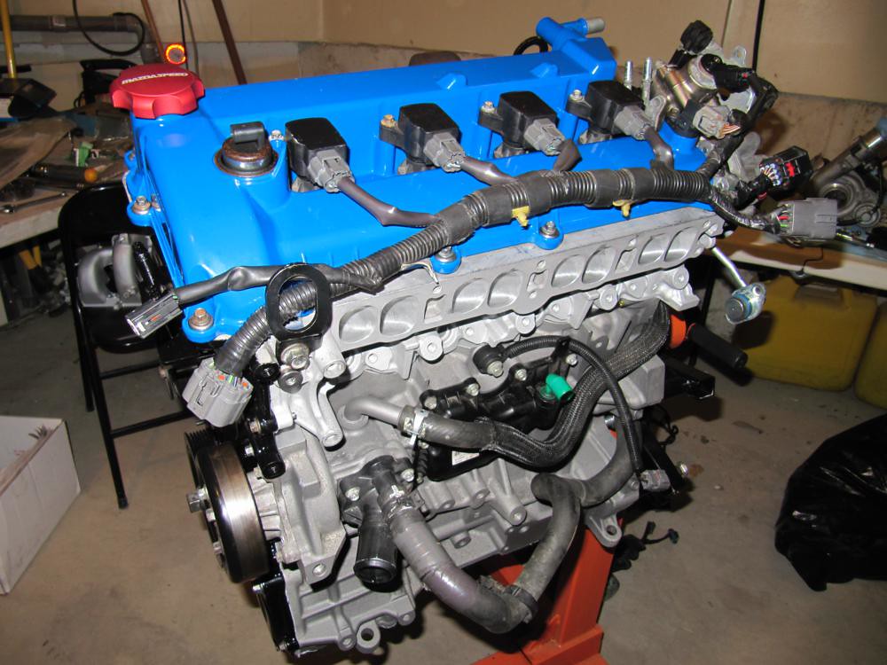
    For those who don't know. I built two forged motors that are identical in every way save for the oil cap; mine is the red aluminum MazdaSpeed unit and the second one is the plastic pos. The first engine is currently in my car and the second one is neatly packaged in the house looking for a new home.

    The pictures below were taken from both builds. If you see a mild change of scenery, you'll know why. Also, towards the end, the pictures get a little spotty (I'm missing a few) so I'll try to explain it as best as possible.

    Onto the walkthrough.

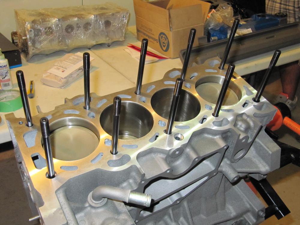
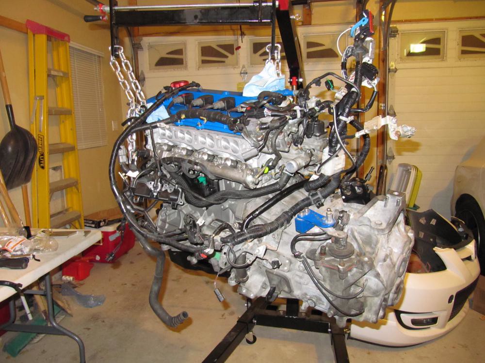
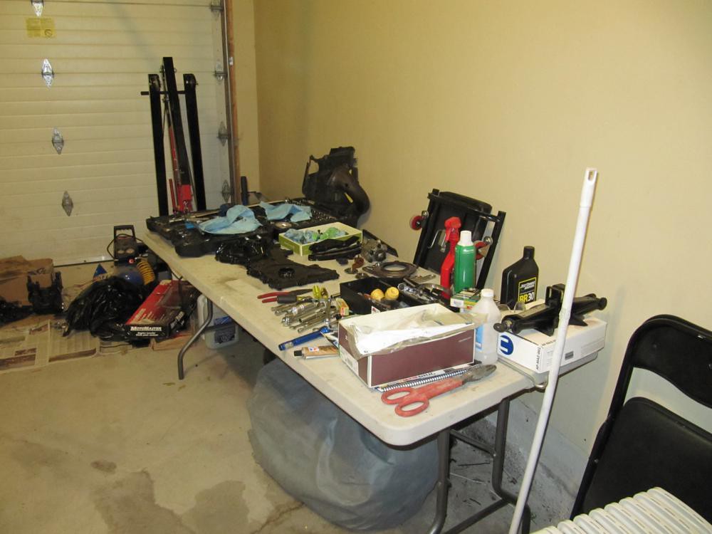
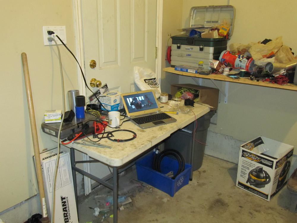
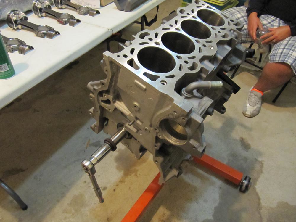
    Prepare your workstation and put the block onto the engine stand.

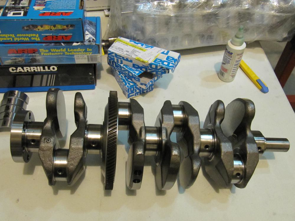
    Lay everything out neatly so you know where it goes. By the end of the assembly, your shit will be everywhere but at least you tried, right?


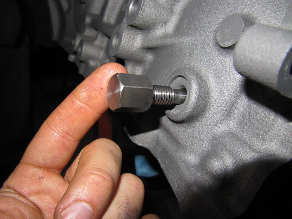
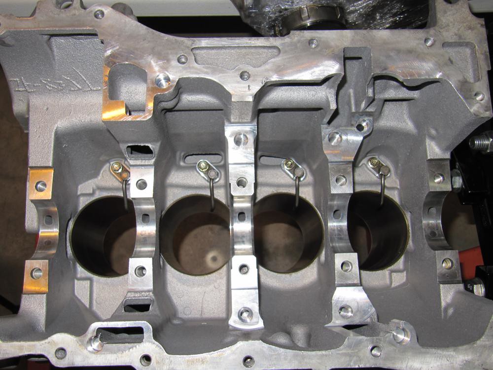
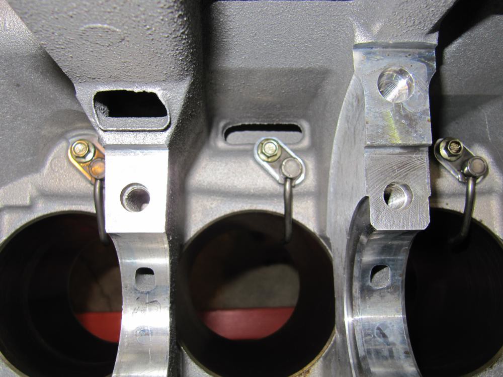
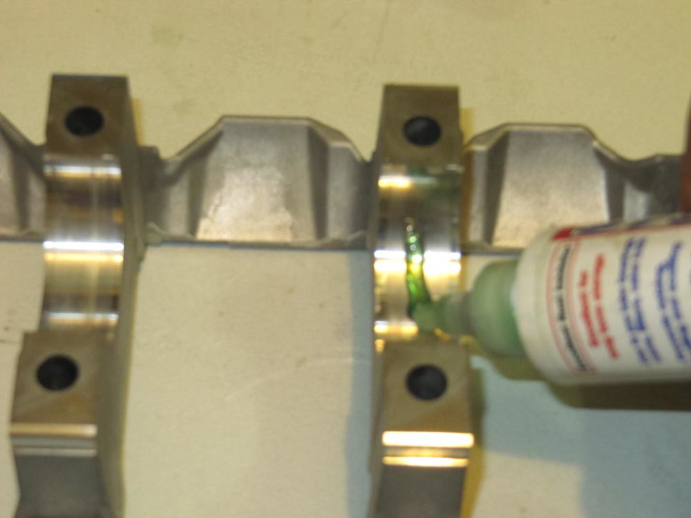
    Grab the oil squirters and attach them to the block. With the Wiseco and Carillo setup, I had to slightly bend the squirter further to the center so the piston skirt wouldn't make contact. Don't bend them too much as you may weaken the metal.


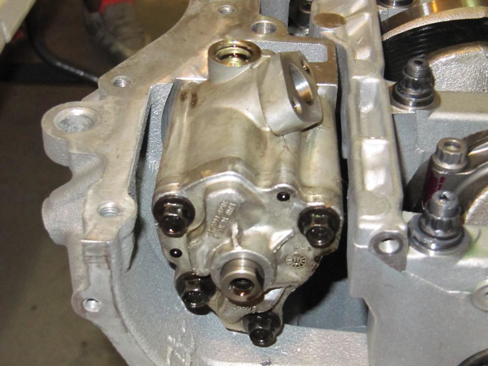
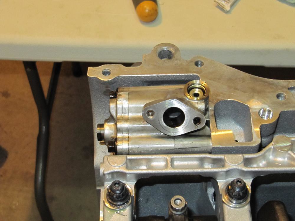
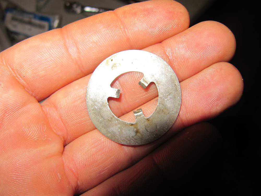
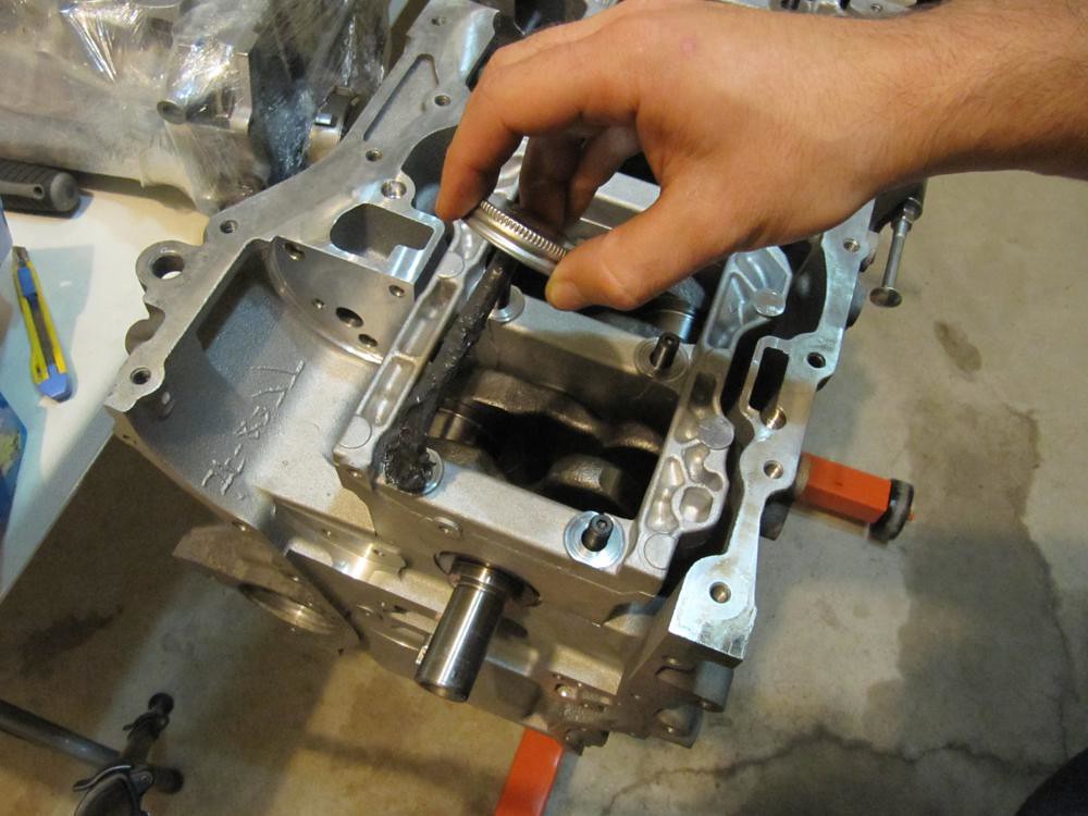
    Prep balance shaft delete kit and install it. I put some threadlock onto the bolts for peace of mind.


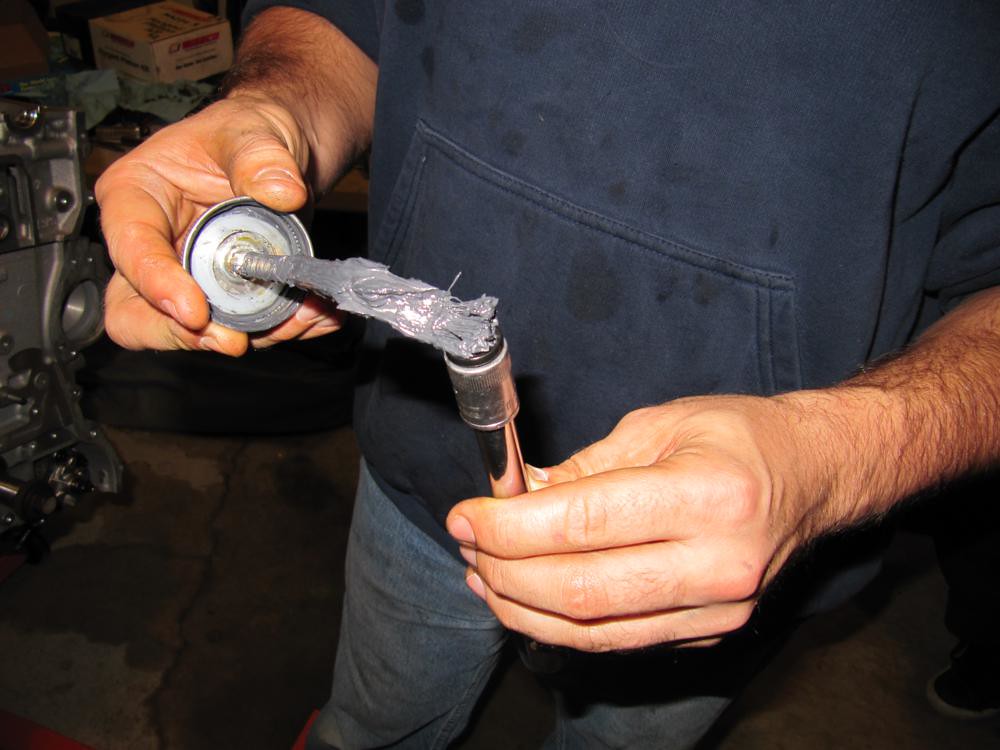
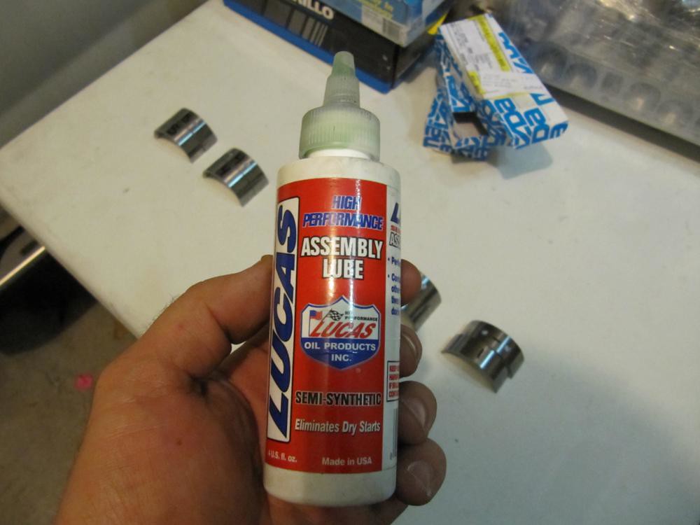
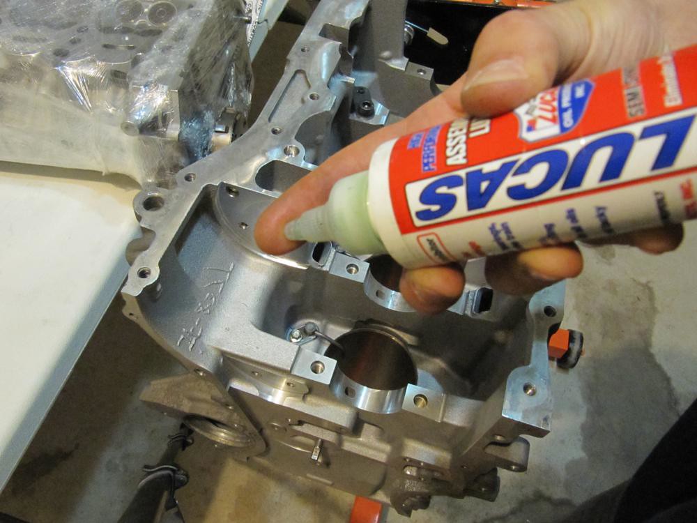
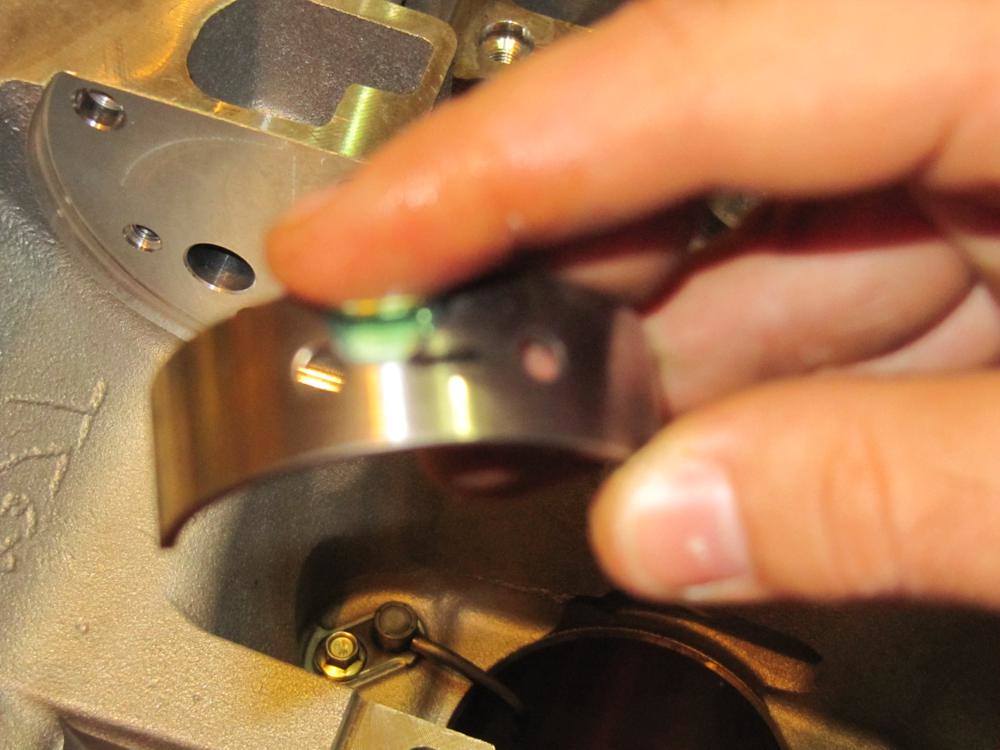
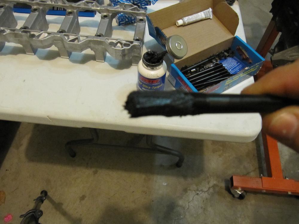
    Grab some assembly lube and with your finger, spread it onto the bearing journal on the block.


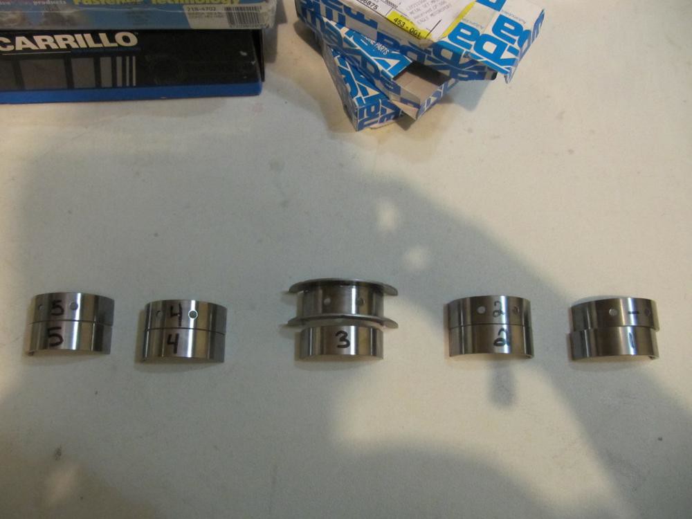
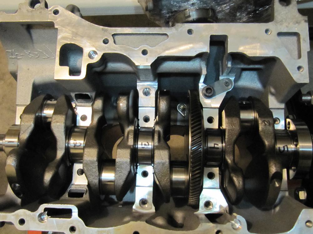
    Lay out the main bearings in order. My engine builder (Competition Automotive) numbered them from 1 to 5. Bearing number 1 goes at the front of the engine (timing chain side). The bearings come in two pieces; ones with oil passages and ones without. The halves with oil passages are positioned on the block side and the halves without get positioned on the girdle side.

    Also notice that the half with the oil passages on bearing 3 is different. This is the thrust bearing and gets mounted on the block side (as mentioned earlier).


    Grab the bearing halves with the oil passages, apply assembly lube on the inside of the bearing with your finger then position them on the block. Make sure they are properly centered in the journal.


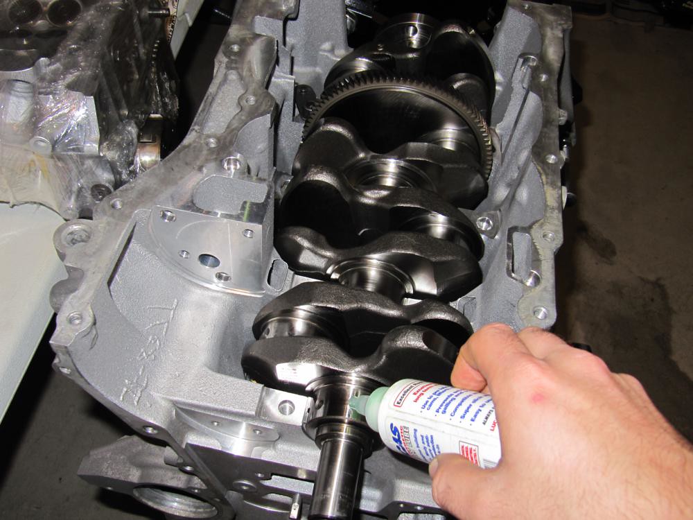
    Next, grab the crank and drop it in (slowly!).


    Apply assembly lube onto the main bearing portion of the crank in preparation for the other bearing halves.


    Position the bottom halves of the bearings onto the crank in numbered order.


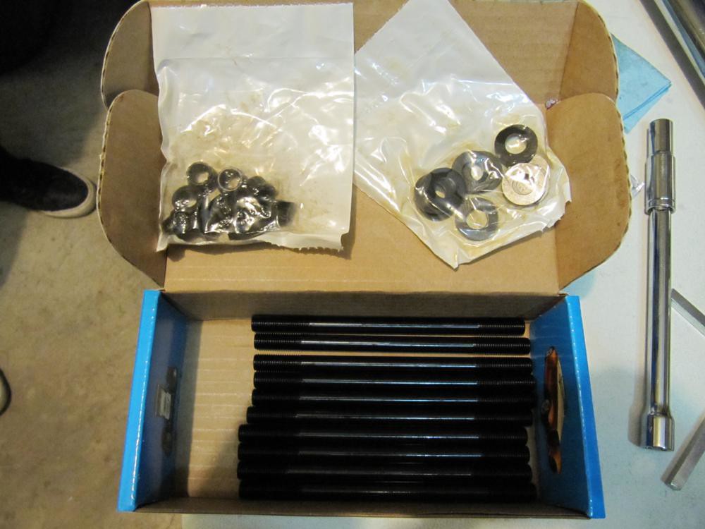
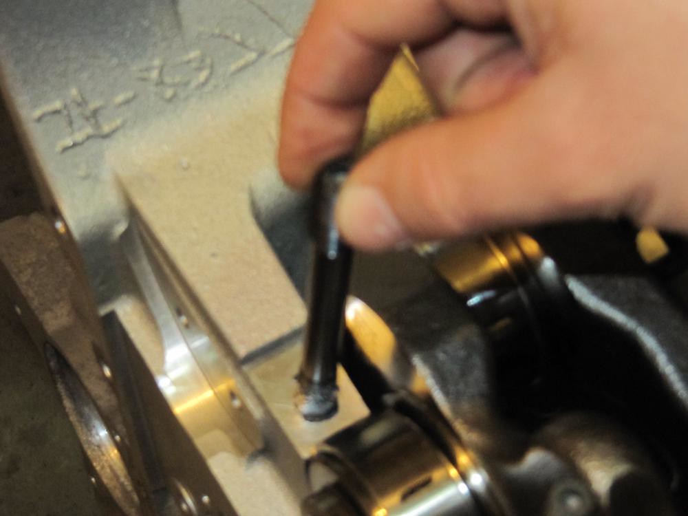
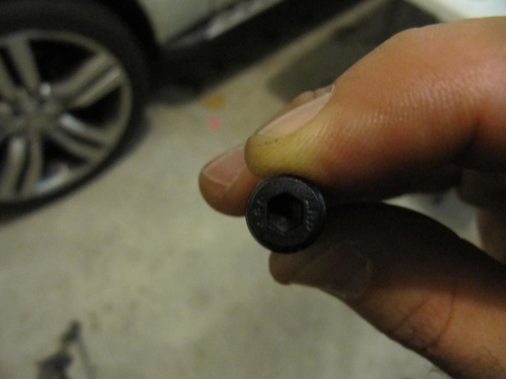
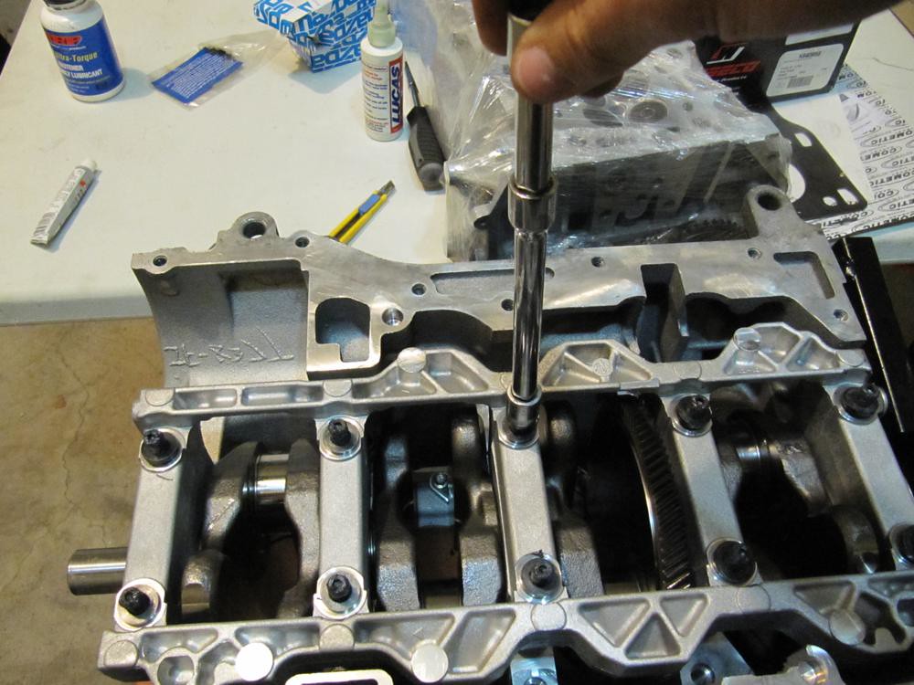
    Grab your ARP MAIN studs and apply a generous amount of ARP Ultra-Torque lube onto the threaded portion without the hex shape on the end. Thread the studs into the block.


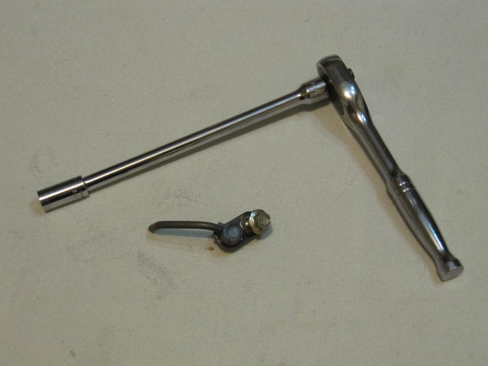
    There are 10 main studs total. I found that it took a while to thread these things in without some assistance so I grabbed the proper hex head, put it on a screw driver handle and went to town. Be sure that you thread the studs all the way down until they stop. DO NOT ADD TORQUE TO THE STUDS ONCE THEY BOTTOM OUT AND DO NOT USE POWER TOOLS. If you do either, you should be slapped.


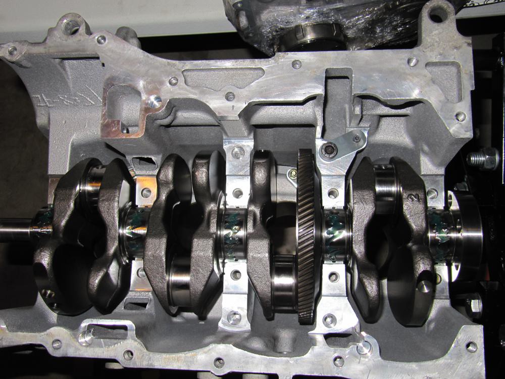
    Apply assembly lube to the girdle journals. Don't be stingy but don't go nuts (this applies to using the lube on any necessary surface on the motor).


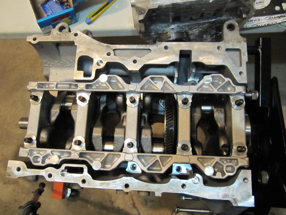
    Gingerly align the girdle onto the studs and drop it in. The girdle only fits in one way without resistance. If you fail at putting together a puzzle, don't assemble a motor.


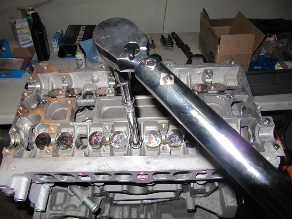
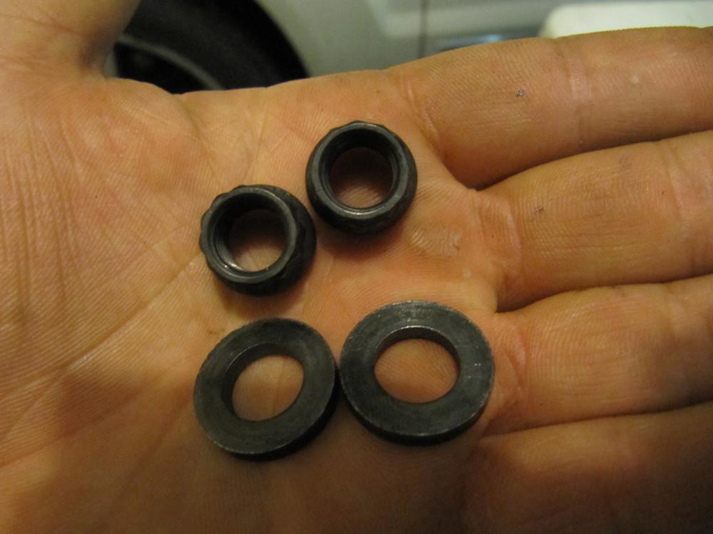
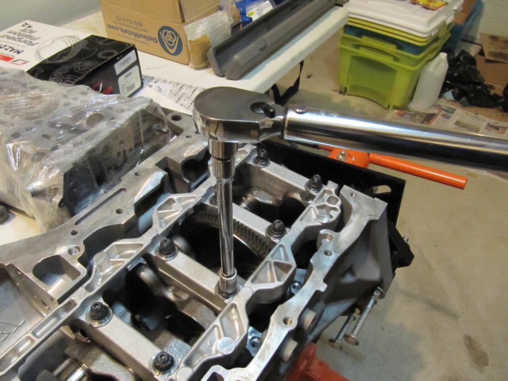
    Grab the ARP Ultra-Torque lube and apply it liberally to the stud tops. Then, insert the washers and nuts accordingly. Hand tighten them down.


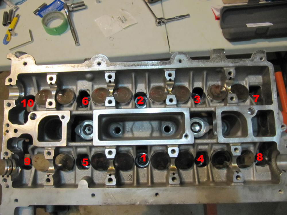
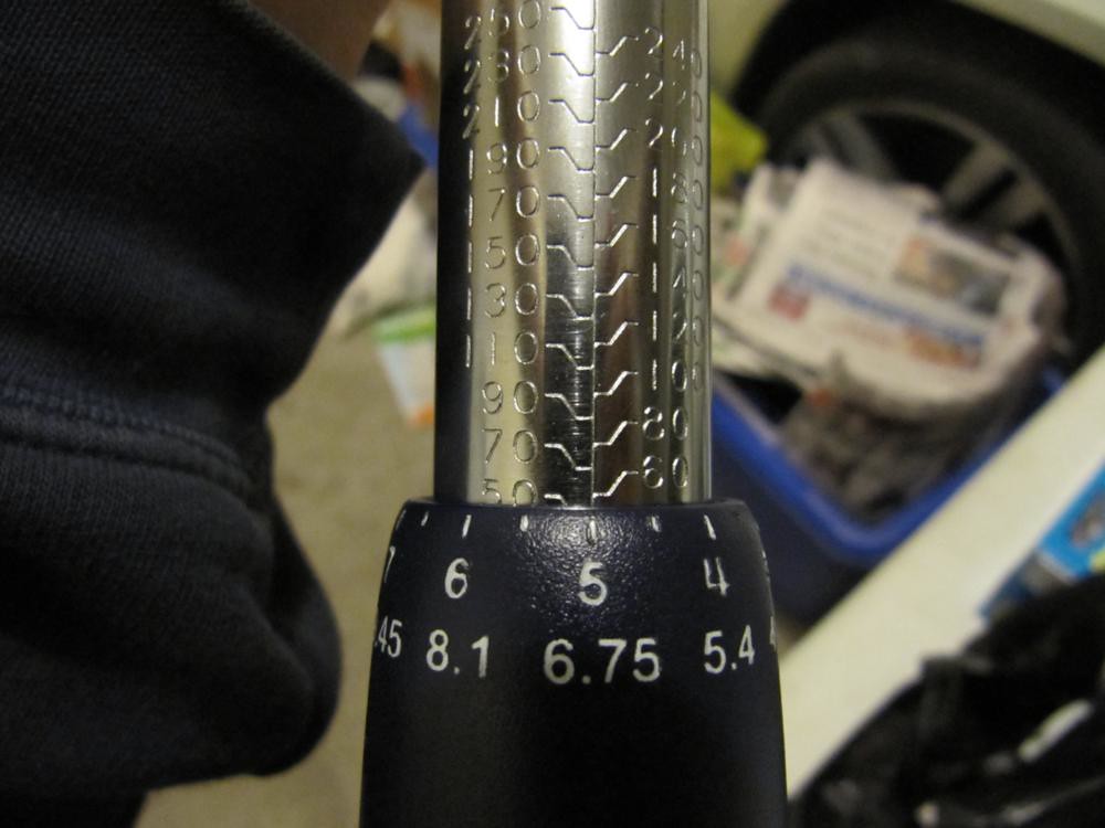
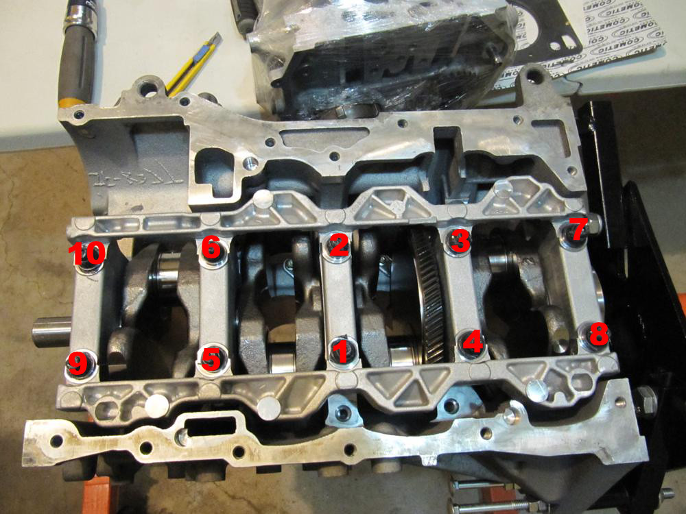
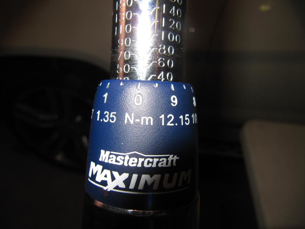
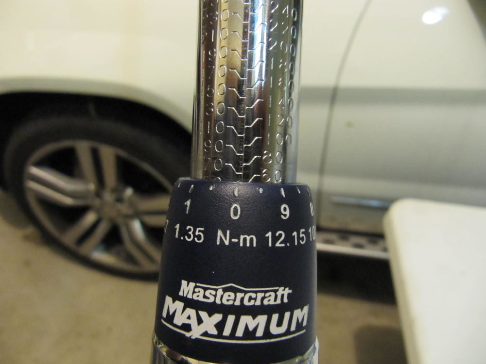
    ARP recommends tightening the girdle down in 3 passes to a maximum of 60ft-lbs.

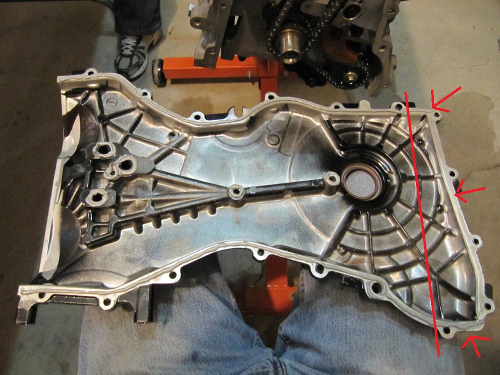
    Ensure you tighten them in the proper order (pictured below) in 20ft-lbs increments.


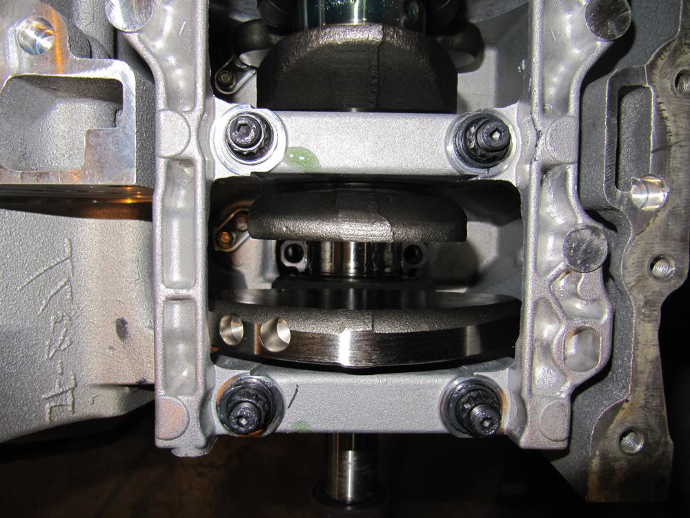
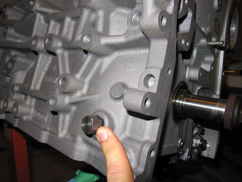
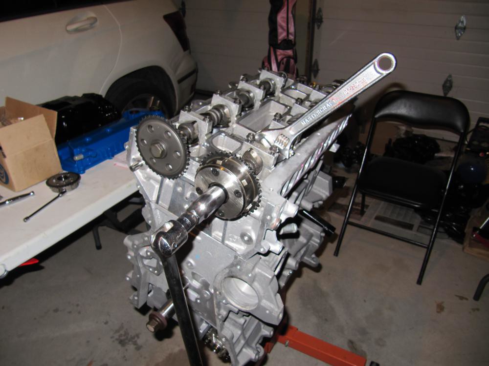
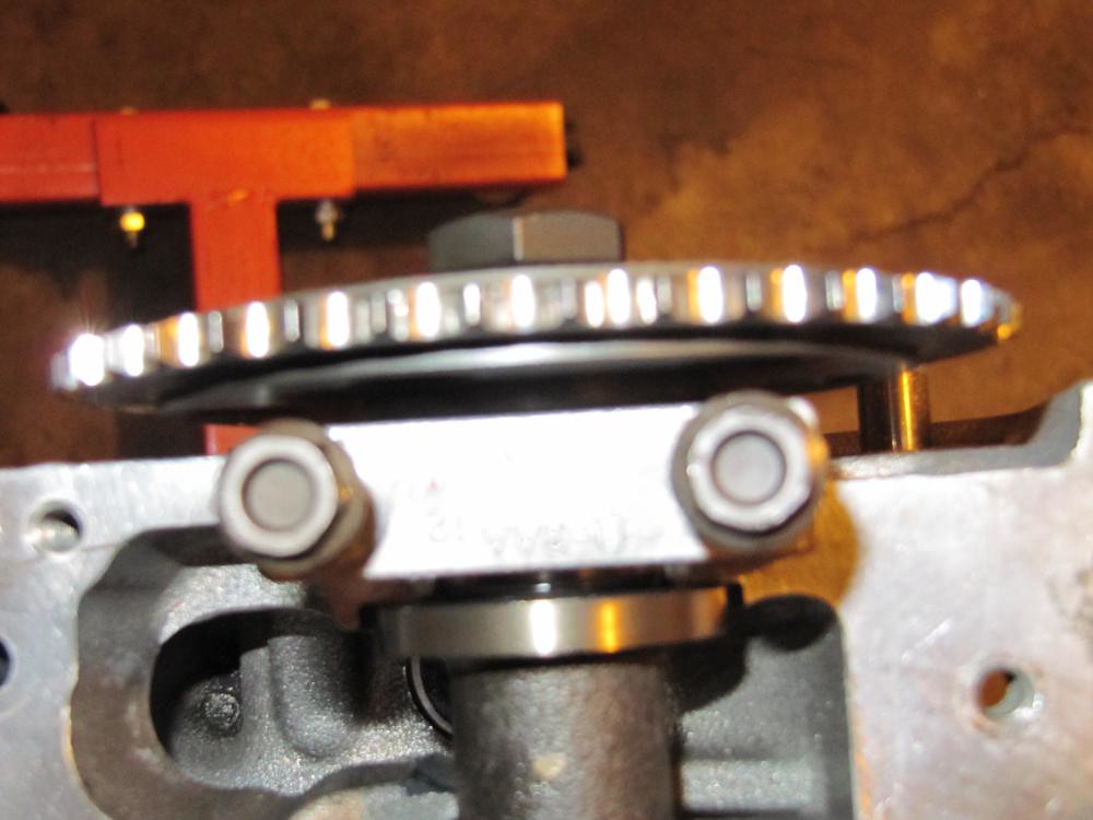
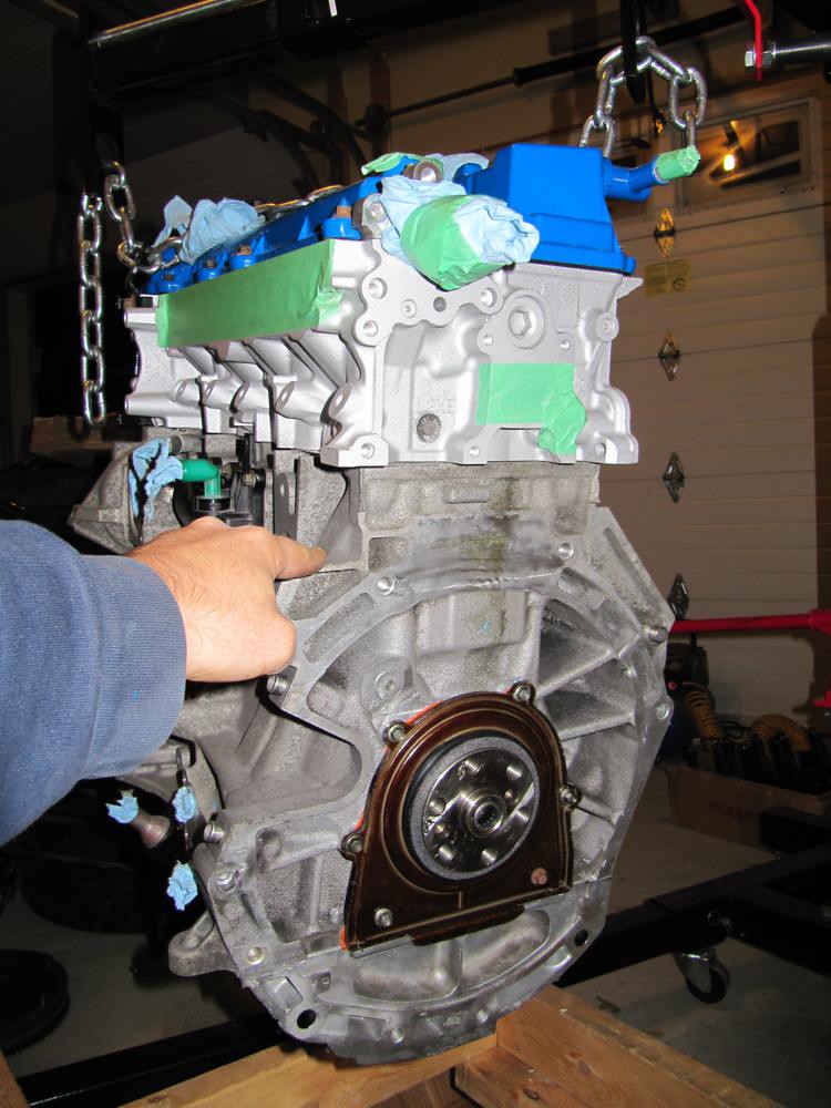
    The crank is now securely fastened. Rotate the block upright for the next phase of the build. Also, grab your old crank pulley bolt and thread it into the crank; it'll become quite useful.


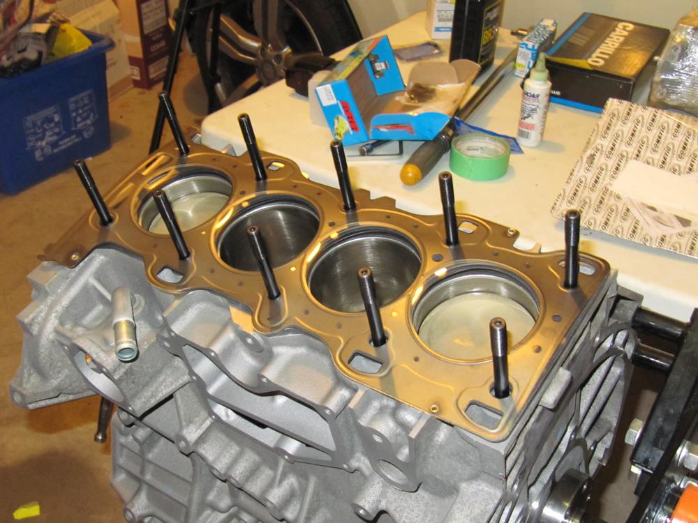
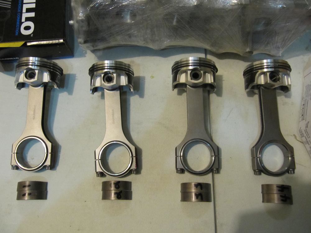
    Lay your piston/rod (with rings) assemblies and corresponding rod bearings onto a flat surface. I had Competition Automotive assemble the piston to the rod for a small fee. On the second motor (pictured here), the also put the rings on. Unfortunately, I don't have pictures of the ring install from the first motor so I'm going to skip this step.


    Grab piston/rod number 1, remove the rod cap, apply lube to the inner AND outer portion of the bearing halve for rod 1 and press it in. It'll require the tiniest bit of force for it to seat properly. Note the notch on the upper right-hand corner of the rod and the corresponding notch in the bearing; they only seat one way.


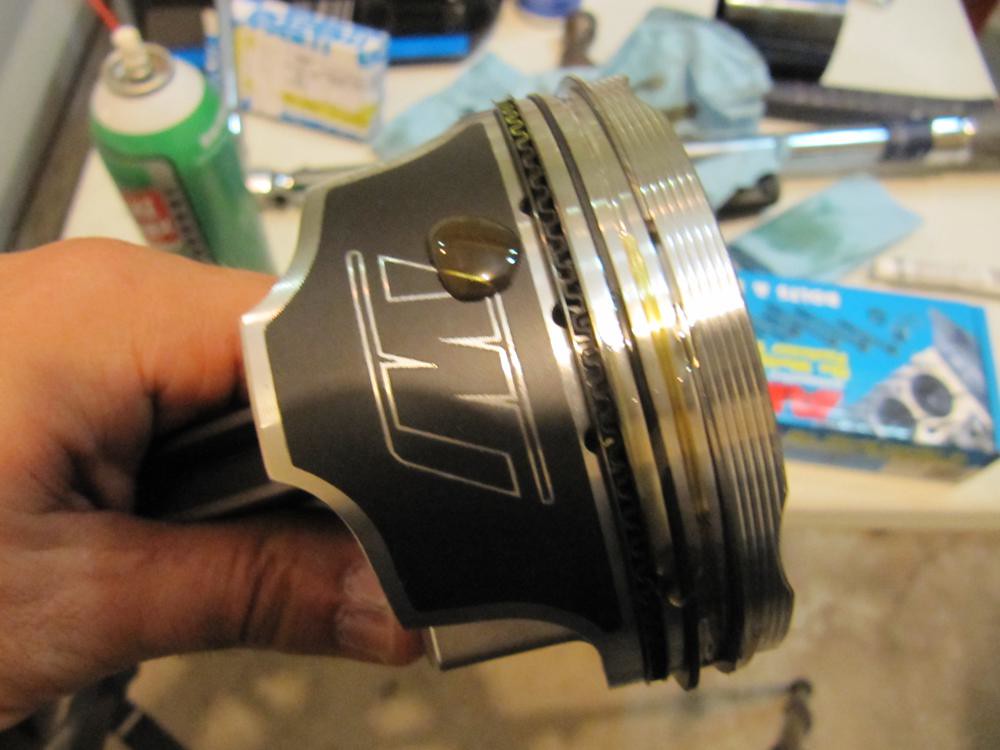
    Apply some motor oil to the outside of the piston. Don't be stingy but don't go nuts; apply enough.

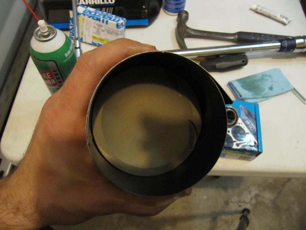
    Then, position the piston/rod combo into your ring compressor tool. Ensure the piston top is parallel to the top of the ring compressor and that the piston skirt hangs out juuuust a little; it'll help with alignment.


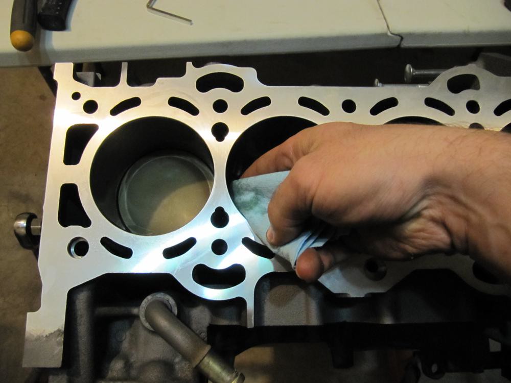
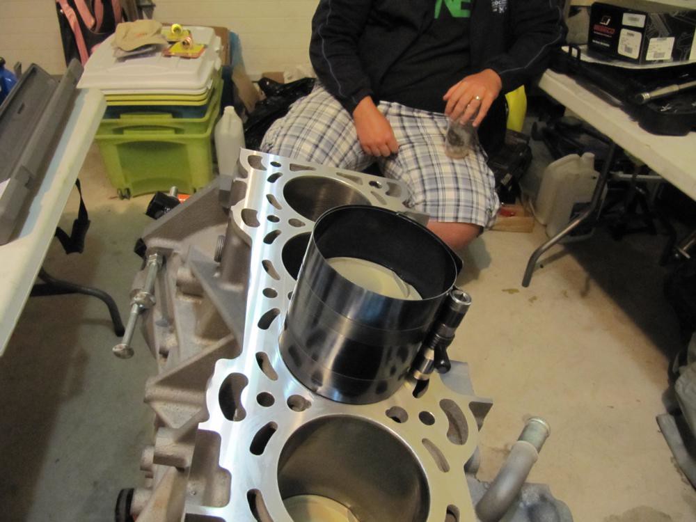
    Stuff a shop towel down the cylinder bore to prevent the rod from nicking the crank when it drops in. Lube the inside of the cylinder wall with some motor oil then position the piston/rod combo with ring compressor on top. Ensure the ring compressor tool is perfectly centered AND that the valve reliefs on the piston tops are facing the PCV/water pump side of the engine.


    While holding the compressor tool with one hand, use the rubber handle of a hammer to gently tap the piston/rod down the cylinder bore. Competition Automotive said I could do it in one shot but I was too much of a wuss to do it that way; I went with the multiple-gentle-tap method. (not pictured unfortunately).

    IF you feel any sort of resistance while trying to tap the piston/rod down the bore, chances are one of the rings is resting on top of the block surface which is preventing the whole assembly from going in. Remove the piston/rod, reposition it in the ring compressor and try again.
    Last edited by BlueStreak; 01-16-2012 at 02:25 PM.

  2. #2
    Sponsor
    BlueStreak's Avatar
    Join Date
    Oct 2007
    Posts
    1,183
    Thanks
    39
    Thanked 34 Times in 13 Posts
    Mentioned
    34 Post(s)
    Tagged
    0 Thread(s)

    Default Re: How To: Assemble A Forged MZR DISI Motor

    Once the piston/rod slides down the bore, flip the block upside-down, remove the shop towel and gently align the rod with the corresponding position on the crank.

    Note the super badass drill holes on the counterweight of the crank. This is done to balance the crank to within .1 grams. These holes are more exaggerated than the crank in OEM trim.


    Apply lube to the exposed portion of the crank.


    Apply lube to the innner AND outer sides of the corresponding bearing and press it into the corresponding rod cap (remember to align the notches in the bearing and cap). Mate the rod cap with the rod and tighten the rod cap bolts to spec. (not pictured; forgot. Bah)

    Generally, you are required to tighten the rod cap bolts to a specific "stretch" up to a certain amount of torque (in ft-lbs). I went with just under the maxiumum torque setting since I didn't have the tools to measure stretch.

    Cylinder 1 is done. Rotate the entire assembly with the crank pulley bolt to ensure there is no binding.


    Repeat the same steps for cylinders 2-4. Once they're all in, rotate the entire assembly again and get blown away at the awesomeness of an assembled short block. Note the positioning of the intake valve reliefs of the piston tops; they are facing the PCV/water pump side of the engine.


    To be continued...

  3. #3
    Sponsor
    BlueStreak's Avatar
    Join Date
    Oct 2007
    Posts
    1,183
    Thanks
    39
    Thanked 34 Times in 13 Posts
    Mentioned
    34 Post(s)
    Tagged
    0 Thread(s)

    Default Re: How To: Assemble A Forged MZR DISI Motor

    Flip the block upside-down again and fasten the oil pump to the block. Don't forget to attach the black plastic pick-up tube as well. The only thing left on the bottom of the block is the oil pan.

    Flip the block right side up when done.


    Next up are the ARP Head Studs (they are longer than the mains). Use the same approach as the mains. Apply ARP Ultra-Torque Lube to the threaded portion of the stud on the side without the hex and thread it in by hand.

    Again, tighten the studs by hand until they bottom out. Do not go any further. Apply ARP Ultra-Torque Lube onto the exposed threads of the studs.


    Slide on the head gasket.


    Insert the TDC crank tool into the proper blind plug hold in the side of the block adjacent to cylinder 1. Rotate the crank until the counterweight makes contact with the tool. Visually inspect the position of cylinder 1 to ensure you're at TDC.


    Slowly lower the head onto the shortblock. In this picture the cams are on the head but they are not tightened down. You could just as easily remove the cams BEFORE putting the head on the block (they will have to be removed for the next step anyways).


    Remove the cams and caps and set them aside...

    Place one (supplied) washer onto each head stud. Apply lube to the nut head, the threads and the socket to make it easier to fasten. If you don't lube the socket, it'll be a PITA since the nut will keep falling out. Thanks to DJ for that suggestion.


    Hand tighten the nuts into the studs then torque them in 3 passes to 60ft-lbs using the order below. Other have tightened the head studs to 80-90ft-lbs to prevent the head from lifting at high boost. I've been running 25PSI through my setup using ARPs recommendation and haven't had an issue so far.


    If you haven't dropped in the valve buckets, do so now. Make sure they were labelled before the engine was disassebled (Intake 1, Intake 2 etc... and Exhaust 1, Exhaust 2 etc...) as you have to put them back in the exact order for proper valve lash. If you forgot which goes where, god help you.


    If you ordered a DCR VVT upgrade, you can swap it in now. Start off by drawing two lines that extend from the cam and onto the back of the VVT sprocket where the two mate. This will act as a reference for the new VVT since it the new one has to be oriented EXACTLY (!!!) like the original.


    Use an adjustable wrench or open end wrench to secure the cam with one hand (on the hex portion of the cam) and a ratchet on the other. It shouldn't take too much effort to get it loose. There's a friction washer in there; replace it with a new one.


    There's a chance that the crank may have turned since you last secured it to the TDC SST. Go back and make sure that cylinder 1 is at TDC.


    If, like me, you don't have a table vise, throw the intake cam on the head. Securing the cam to the head will act as a third hand for the steps that follow. Ensure the orientation of the intake cam lobes look like the following and throw on the SST onto the back of the cam prior to torquing the cam caps onto the head. (Ignore the fact that the exhaust cam is on the head for the moment; I didn't have a picture without).

    IF you torque down the intake cam without ensuring that a) cylinder 1 is at TDC and b) the cam lobes are aligned as pictured, there's a very high chance the valves will make contact with the pistons and you'll end up bending the valves.


    Slide on the DCR VVT (properly aligned - remember those markings you made?), secure the cam with a wrench then tighten the cam bolt to 50ft-lbs using a torque wrench. After you have tightened it, make sure the VVT didn't rotate relative to the markings on the sprocket/cam.


    Next, install and secure the exhaust cam onto the head (see previous photos for proper cam lobe orientation). Loosen the bolt securing the exhaust sprocket to the cam. Do not remove the sprocket, though. Just let it freewheel for now. Make sure you tighten the cam caps while the cam is aligned with the SST.


    Install the VVT actuator onto the head.


    Remove the crank pulley bolt from the crankshaft. There's a chance that when backing out the bolt, the crank will turn slightly and no longer be at TDC. Reach underneath the block and push on the balance shaft gear to ensure cylinder 1 is still at TDC. This is very important. (not pictured)

    Slide one (new) friction washer onto the front of the crank then the oil pump sprocket. Ensure you're putting on the oil pump sprocket and not the timing chain sprocket; they are different.


    Dangle the oil pump chain onto the crank sprocket then install the keyed oil pump sprocket onto the oil pump. There's a SST for this but I just jammed a screwdriver through the keyed sprocket and tightened the bolt; torque specs aren't that high. See the manual for the proper torque.


    Install the oil pump chain guide (black piece on the bottom) and the tensioner (orange thingy). Be sure to add some assembly lube where the chain meets the guide. Its straight forward hence the automotive terms like "black piece" and "orange thingy"...


    Dangle the timing chain on the intake/exhaust sprockets.


    Slide another friction washer onto the front of the crank then insert the timing chain sprocket with the timing chain attached. You should be able to get it on after a few F bombs.


    Slide on the last friction washer.


    Attach the timing chain guide (on the right) then the tensioner arm on the left (add some assembly lube onto the surface where the chain meets the guide). The guide on the right is secured by two bolts and the tensioner arm on the left just slides onto the dowel pin on the head.


    Compress the timing chain tensioner and jam it with a paper clip on the locking mechanism (not pictured; shoot). Install the tensioner onto the block then remove the paper clip. The tensioner should push out onto the tensioner arm and make the timing chain taut.


    Insert a new front seal onto the timing chain cover, spread a bead of Permatex sealant around the perimeter of the cover as well as the interior bolt holes then install it on the block. See the instruction manual for proper front seal depth and bolt size placement.


    To be continued...
    Last edited by Aitch; 01-18-2012 at 10:35 AM.

  4. #4
    Member breakfasteatre's Avatar
    Join Date
    Jan 2011
    Posts
    1,385
    Thanks
    17
    Thanked 130 Times in 70 Posts
    Mentioned
    35 Post(s)
    Tagged
    0 Thread(s)

    Default Re: How To: Assemble A Forged MZR DISI Motor

    Dave, you are the man. I wont ever be doing this (crosses fingers) but i still went through it, great photos and hilarious descriptions
    Oh damn, that sucks. Oh well, I stopped reading the Speed section because according to certain people only speed owners are allowed to even look at that section.

  5. #5
    Moderator Mr Wilson's Avatar
    Join Date
    Jan 2010
    Location
    Toronto
    Posts
    4,621
    Thanks
    1,341
    Thanked 700 Times in 381 Posts
    Mentioned
    227 Post(s)
    Tagged
    0 Thread(s)

    Default Re: How To: Assemble A Forged MZR DISI Motor

    ^^^ +1, glad I could be the background model!
    0.000212524463 gigawatts

  6. #6
    Moderator loki's Avatar
    Join Date
    Mar 2011
    Location
    Toronto
    Age
    42
    Posts
    18,049
    Thanks
    1,911
    Thanked 6,154 Times in 3,173 Posts
    Mentioned
    881 Post(s)
    Tagged
    1 Thread(s)

    Default Re: How To: Assemble A Forged MZR DISI Motor

    Good write up!

    I have extra plastic POS oil cap if you wanna trade so both yours match?!? Yes? No?

    Faaak

  7. #7
    Sr Member rzapata's Avatar
    Join Date
    Jan 2011
    Location
    Downtown TO
    Posts
    4,502
    Thanks
    191
    Thanked 135 Times in 86 Posts
    Mentioned
    36 Post(s)
    Tagged
    0 Thread(s)

    Default Re: How To: Assemble A Forged MZR DISI Motor

    This is probably why the build took a bit longer too. I can't imagine taking pictures every step of the way.

    Good stuff Dave!

  8. #8
    Member Elusivellama's Avatar
    Join Date
    Feb 2010
    Ride
    2010 MS3 (black mica)
    Posts
    1,456
    Thanks
    10
    Thanked 12 Times in 10 Posts
    Mentioned
    9 Post(s)
    Tagged
    0 Thread(s)

    Default Re: How To: Assemble A Forged MZR DISI Motor

    I love seeing something like a motor being assembled... very fascinating stuff. Beautiful pistons too

  9. #9
    Member Booostin's Avatar
    Join Date
    May 2011
    Location
    Brampton
    Ride
    Your Mom
    Posts
    2,082
    Thanks
    6
    Thanked 23 Times in 13 Posts
    Mentioned
    4 Post(s)
    Tagged
    0 Thread(s)

    Default Re: How To: Assemble A Forged MZR DISI Motor

    Looking good so far... oh and nice Benz


  10. #10
    Sr Member boyracer's Avatar
    Join Date
    May 2008
    Location
    NATOR T.O. Outpost
    Ride
    Vapour Trail
    Posts
    4,588
    Thanks
    621
    Thanked 358 Times in 201 Posts
    Mentioned
    117 Post(s)
    Tagged
    0 Thread(s)

    Default Re: How To: Assemble A Forged MZR DISI Motor

    Very good read

  11. #11
    Jr Member
    Join Date
    Sep 2011
    Location
    Ottawa
    Posts
    303
    Thanks
    11
    Thanked 2 Times in 2 Posts
    Mentioned
    3 Post(s)
    Tagged
    0 Thread(s)

    Default Re: How To: Assemble A Forged MZR DISI Motor

    Subscribed, great write up

  12. #12
    Moderator loki's Avatar
    Join Date
    Mar 2011
    Location
    Toronto
    Age
    42
    Posts
    18,049
    Thanks
    1,911
    Thanked 6,154 Times in 3,173 Posts
    Mentioned
    881 Post(s)
    Tagged
    1 Thread(s)

    Default Re: How To: Assemble A Forged MZR DISI Motor

    Quote Originally Posted by boyracer View Post
    Very good read
    who you trying to kid, you didn't read it, you looked at the pictures!

    that's what I did...

  13. #13
    Sr Member Thrizzl3's Avatar
    Join Date
    Jul 2008
    Age
    36
    Ride
    '18 Subaru WRX / '20 CX9
    Posts
    18,375
    Thanks
    430
    Thanked 500 Times in 260 Posts
    Mentioned
    265 Post(s)
    Tagged
    0 Thread(s)

    Default Re: How To: Assemble A Forged MZR DISI Motor

    Quote Originally Posted by lokiaparandi View Post
    who you trying to kid, you didn't read it, you looked at the pictures!

    that's what I did...
    not going to lie i did the thing...and some reading lol

  14. #14
    Sponsor
    BlueStreak's Avatar
    Join Date
    Oct 2007
    Posts
    1,183
    Thanks
    39
    Thanked 34 Times in 13 Posts
    Mentioned
    34 Post(s)
    Tagged
    0 Thread(s)

    Default Re: How To: Assemble A Forged MZR DISI Motor

    Thanks gents.

    More info added. Almost done.
    Last edited by Aitch; 01-18-2012 at 10:35 AM.

  15. #15
    Jr Member horto's Avatar
    Join Date
    Aug 2009
    Posts
    907
    Thanks
    1
    Thanked 1 Time in 1 Post
    Mentioned
    16 Post(s)
    Tagged
    0 Thread(s)

    Default Re: How To: Assemble A Forged MZR DISI Motor


    Quote Originally Posted by BlueStreak View Post
    We don't recirculate our boost, we vent that hoe to the atmosphere. We don't suggest standing in the same room with this thing goes off. The pressure change will be so great that when ambient pressure returns to normal, you'll die from the bends.

  16. #16
    Sponsor - Mspeed Tuning & Diagnostics
    -cj-'s Avatar
    Join Date
    Mar 2008
    Age
    45
    Posts
    1,762
    Thanks
    21
    Thanked 18 Times in 8 Posts
    Mentioned
    21 Post(s)
    Tagged
    0 Thread(s)

    Default Re: How To: Assemble A Forged MZR DISI Motor

    Sooo bad ass. Like I said before, you make it all sound and look easy.

  17. #17
    Sr Member boyracer's Avatar
    Join Date
    May 2008
    Location
    NATOR T.O. Outpost
    Ride
    Vapour Trail
    Posts
    4,588
    Thanks
    621
    Thanked 358 Times in 201 Posts
    Mentioned
    117 Post(s)
    Tagged
    0 Thread(s)

    Default Re: How To: Assemble A Forged MZR DISI Motor

    Quote Originally Posted by lokiaparandi View Post
    who you trying to kid, you didn't read it, you looked at the pictures!

    that's what I did...
    LOL, Shut it! I actually did read the whole thing.

  18. #18
    Jr Member
    Join Date
    Sep 2011
    Location
    Ottawa
    Posts
    303
    Thanks
    11
    Thanked 2 Times in 2 Posts
    Mentioned
    3 Post(s)
    Tagged
    0 Thread(s)

    Default Re: How To: Assemble A Forged MZR DISI Motor

    This thread is awesome, I am learning so much about my engine.

    Now if I could only find the $$$ and the time, and the boatloads of patience to do this myself, oh and a garage would help

    Great stuff

  19. #19
    Member Booostin's Avatar
    Join Date
    May 2011
    Location
    Brampton
    Ride
    Your Mom
    Posts
    2,082
    Thanks
    6
    Thanked 23 Times in 13 Posts
    Mentioned
    4 Post(s)
    Tagged
    0 Thread(s)

    Default Re: How To: Assemble A Forged MZR DISI Motor


  20. #20
    Sponsor
    BlueStreak's Avatar
    Join Date
    Oct 2007
    Posts
    1,183
    Thanks
    39
    Thanked 34 Times in 13 Posts
    Mentioned
    34 Post(s)
    Tagged
    0 Thread(s)

    Default Re: How To: Assemble A Forged MZR DISI Motor

    Write up is complete.

    Enjoy.

    Can a mod move this up? Thanks!
    ------------------------------------------------------

    Ok. So this is where the photos get a little spotty. I'll try to be as specifc as possible.

    Slide on the crank pulley onto the crankshaft. If you followed the steps up until now, the final friction washer should already be installed.

    One of the spokes on the crank pulley has a hole in it. Align that spoke so that it is pointing downward. Directly behind the crank pulley hole now should be a threaded hole for a 6mm (I think) bolt on the timing cover. Grab a 6mm bolt and pass it through the crank pulley hole and thread it into the timing cover. No need to torque the bolt too tight; you might end up snapping it. All you need it for is to hold the crank pulley in position for the next few steps.

    Thread in the crank pulley bolt by hand until it stops.

    *Ignore the fact that the picture has the oil pan and valvecover mounted. We're not there yet.*


    This part is very important now.

    Go back and make sure that a) the cam SST is still in place b) the front cam lobes are properly aligned (the first sets of lobes on each cam point upward and toward each other) and c) cylinder 1 is still at TDC.


    Once you have verified everything is in place, its time to torque the crank pulley bolt. Grab your torque wrench and set it to 90ft-lbs. Torque the crank pulley bolt until the torque wrench clicks.

    Next. With a permanent marker, scribe a straight line through the edge of the crank pulley bolt, crank pulley washer and crank pulley.

    *Go to the kitchen, eat your wheaties and a shit ton of Popeye's spinach*
    Grab a biiiigggg effing breaker bar with a pipe extension and tighten the pulley bolt an additional 90 degrees (if you don't at least have a breaker bar for this step, go buy one). Use the markings on the crank pulley bolt and crank pulley to indicate where you are at. Once the marking on the crank pulley bolt is 90 degrees relative to the crank pulley, you're done.

    *Ignore the fact that the picture has the oil pan and valvecover mounted. We're not there yet.*


    Now, its time to tighten the exhaust cam sprocket onto the cam. Grab your adjustable or open end wrench and position it on the hex portion of the cam (just behind cylinder 1). Grab another wrench and position it on the sprocket bolt. Holding the wrench on the hex portion of the cam steady, tighten the bolt to 50ft-lbs (I went by feel here). The trick is to not let the cam rotate at all when tightening (there's a bit of play in the SST) and let the bolt wrench do all the work.


    Go back and remove the bolt that secures the crank pulley to the timing cover, the TDC pin and the cam SST.

    For shits, giggles and awesomeness. Throw a ratchet onto the crank pulley bolt and spin the entire assembly. If you don't have spark plugs in the head, it should be pretty easy to rotate.

    Flip the block upside down in preparation for the oil pan installation.

    Part of the timing cover hangs below the short block. If you recall, we spread a bead of Permatex sealant around the entire perimeter earlier. Well, some of that Permatex never made contact with anything and has probably dried up by now. Wipe the excess off.


    Spread a bead of Permatex sealant around the perimeter of the oil pan. Don't forget to put a bead on the portion where the oil pan meets the back of the timing cover.

    Lower the oil pan onto the block and install all the bolts. Make sure your drain plug is on as well (no picture unfortunately).

    Flip the block right-side up and install the valvecover. Your engine should now look something like this.


    If it looks like a barn, you did it wrong (Simpsons, anyone?).

    Get the engine assembly on a hoist for the final piece; the rear main seal. I spread a bead of Permatex in the following manner; the Mazda manual omits the bottom portion. There was nothing to lose which was why I did it the way I did.

    *NOTE: The bead of Permatex was spread on the INSIDE of the rear main seal. I do not have the proper photo*


    Install the rear main seal using the supplied install tool. All you need to do is position the seal onto the block, tighten the 6 bolts then remove the install tool (you'll know exactly what I mean when you see it).


    DONE!

    Throw on more parts and it'll really start to look sexy.


    If I missed anything, let me know.

    Cheers

  21. #21
    Sponsor - GTA Retrofits
    Hyperion's Avatar
    Join Date
    Dec 2010
    Location
    Richmond Hill
    Age
    34
    Posts
    5,855
    Thanks
    229
    Thanked 1,089 Times in 541 Posts
    Mentioned
    252 Post(s)
    Tagged
    1 Thread(s)

    Default Re: How To: Assemble A Forged MZR DISI Motor

    A round of applause for you.
    Modifications? I've forgotten more than I remember. Click here for the list.

  22. #22
    Paper Jam PCLoadLetter's Avatar
    Join Date
    Jul 2009
    Age
    38
    Posts
    1,810
    Thanks
    0
    Thanked 11 Times in 4 Posts
    Mentioned
    5 Post(s)
    Tagged
    0 Thread(s)

    Default Re: How To: Assemble A Forged MZR DISI Motor

    Quote Originally Posted by horto View Post
    +1 !

    Amazing thread, props to you on the build BlueStreak
    Have you seen my stapler?

  23. #23
    Noob
    Join Date
    Mar 2013
    Posts
    3
    Thanks
    0
    Thanked 0 Times in 0 Posts
    Mentioned
    0 Post(s)
    Tagged
    0 Thread(s)

    Default Re: How To: Assemble A Forged MZR DISI Motor

    any chance You can provide torque specs for rod bearings?

  24. #24
    Sponsor
    BlueStreak's Avatar
    Join Date
    Oct 2007
    Posts
    1,183
    Thanks
    39
    Thanked 34 Times in 13 Posts
    Mentioned
    34 Post(s)
    Tagged
    0 Thread(s)

    Default Re: How To: Assemble A Forged MZR DISI Motor

    Quote Originally Posted by alexinvancouver View Post
    any chance You can provide torque specs for rod bearings?
    Torque specs for rod bearings are specific to the rod and supplied bolts. There should be guidance in the instructions included with the rods themselves.

  25. #25
    Noob
    Join Date
    Mar 2013
    Posts
    3
    Thanks
    0
    Thanked 0 Times in 0 Posts
    Mentioned
    0 Post(s)
    Tagged
    0 Thread(s)

    Default Re: How To: Assemble A Forged MZR DISI Motor

    Quote Originally Posted by BlueStreak View Post
    Torque specs for rod bearings are specific to the rod and supplied bolts. There should be guidance in the instructions included with the rods themselves.
    the rods and everything else original.
    engine has 5k on it but due to some damage (i was damaged when i bought it) i had to remove crankshaft
    and now i'm in a process of putting everything back toghether
    also i understand You didn't bother with balancer
    i have to and i don't know the proper way of installing it. can You help?
    thanks

Page 1 of 2 12 LastLast

Similar Threads

  1. Time To Go Forged
    By BlueStreak in forum MazdaSpeed3 Modifications
    Replies: 522
    Last Post: 11-02-2012, 11:46 PM
  2. 2.3L Disi PCV valve maintenance schedule???
    By Kris"Speed3"CWP in forum MazdaSpeed 3 Forum
    Replies: 1
    Last Post: 06-09-2011, 10:05 PM
  3. Forged wheels
    By ShortBus in forum Wheels & Tires
    Replies: 16
    Last Post: 02-26-2009, 11:17 AM
  4. 10 Best Engines 2007 - DISI 2.3L Turbocharged DOHC I-4
    By SpeedBaby in forum MazdaSpeed 3 Forum
    Replies: 5
    Last Post: 12-16-2007, 09:21 PM

Posting Permissions

  • You may not post new threads
  • You may not post replies
  • You may not post attachments
  • You may not edit your posts
  •